|
|
DIY ISD Sound Recorder Project
Heres a little DIY project to build a device that can record multiple
sounds onto an ISD25XX device, based on a kit from Kits'R'Us. It doesn't
offer quite as good audio quality as a Quadravox recorder, but is a tiny
fraction of the cost and gives results that would make most users very
happy.
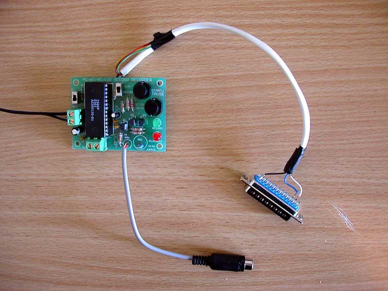
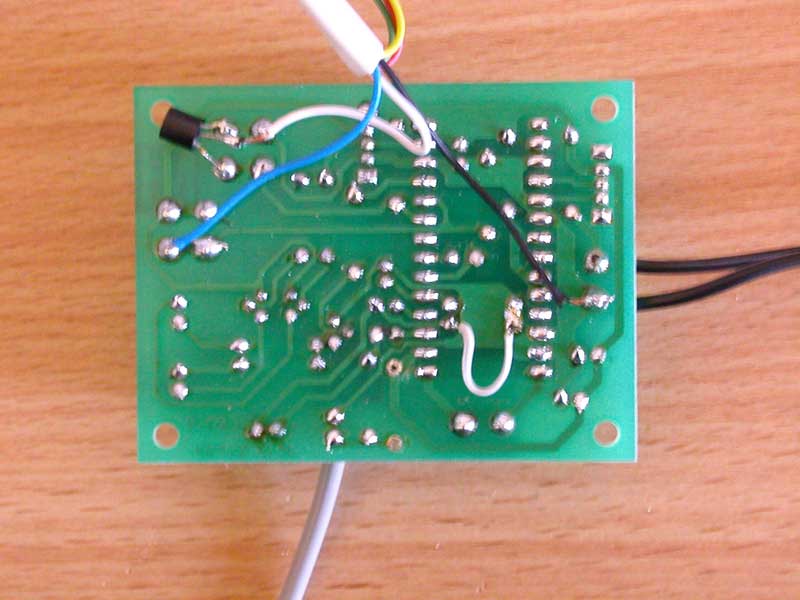
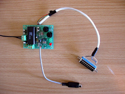
PCB shots (click for larger view)

Parts List:
- K64 120 Second Voice Recorder kit from Ozitronics
(Australia) or Kit-R-Us (International)
Alternatively you could just make your own from scratch
- 25 Pin male D connector and back shell
- 25 pin male to female parallel port extension lead
- RCA line socket
- Short length of sheilded cable, short length of multi-core wire (3
cores minimum)
- 2N7000 Mosfet transistor (or similar TTL input mosfet)
- PC with sound card running any version of Windows
- 1k ohm resistor (any wattage)
- Optional: 28 pin ZIF socket would be a good idea for frequent usage
Assembly:
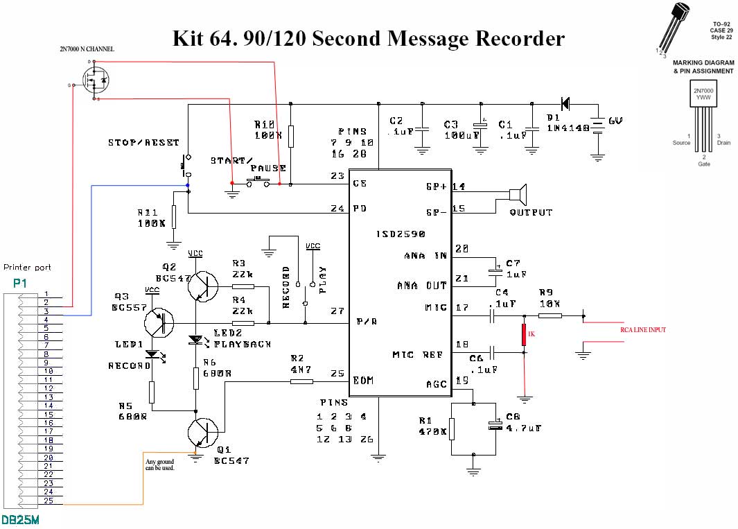
- Refer to schematic, linked below. Changes from the original kit are
marked in colours.
- Assemble the K64 kit, but don't fit R7, R8, C5 or the microphone
- In place of R8, fit a link
- In place of the microphone, fit the 1k resistor
- Where C5 goes, connect a short length of sheilded cable, sheild going
to negative
- Solder the RCA line socket onto the end of the sheilded cable, sheild
to the outside
- Connect 1 wire of the multicore cable to pin 2 (start record), one
to pin 3 (reset) and one to pin 25 (ground)
- Connect the wire from pin 3 to the stop/reset switch on the side that
connects to pin 24 of the ISD (refer pic and schematic for exact details)
- Connect the wire from pin 2 to gate of the 2N7000
- Connect the drain of the 2N7000 to the Start/Pause switch on the side
that connects to pin 23 of the ISD
- Connect the source of the 2N7000 to ground (the other side of the
Start/Pause switch is easiest)
- Connect the wire from pin 25 of the D connector to ground of the board
Schematic (click for larger one:).

Operation:
- Connect the D connector to your parallel port via the extension cable
- Connect the RCA socket to one side of your PC's sound card line output
- Turn on power to the recorder kit
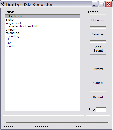
- Start the software
- Open your sounds in the desired order. Load/save your playlist if
desired
- Set the kits slide switch to Record. Set the other one to Norm.
- Press the Record button in the program. You should see the Record
light on the ISD board light up for each sound.
- When its done, flick the kit's slide switch to Play and then press
the Start button on the kit board. For each press you will hear each
sound played.
- If the sounds are distorted, reduce the volume of your soundcard output
and repeat. if they are too quiet, turn it up and repeat.
- If the front of the sound is chopped off, increase the Delay value
in the software. Units of milliseconds, I suggest 30 to 50 as being
suitable. This is to compensate for the ISD's startup delay, and it
delays the start of the playback of each sound.
- When you are happy, stick the ISD in your gun and enjoy.
Software:
The GUI program is written in Visual Basic 6, and hence requires the
VB6 runtime library to be installed (if not already you can get if from
Microsoft's
site.)
Executable is here. Source code is here
(version 1.0 29 May 2004.)
SST's free PortIO driver is required to be installed, to allow access
to the parallel port. Download it here
and install it before trying to use the program. Alternatively, local
mirror of the driver is here.
Notes:
- Software is provided as is, no warantee is given
- No responsibility accepted for any damage to your equipment
- Feedback/questions to Builty, see email on home page or come to www.laserforums.com
|